3D printed keyboard prototype with FreeCAD
10.02.2026In the previous post we used kle-ng to tweak an ergogen layout - adjusting column splay, shifting keys, and mirroring halves. Now we will take that layout, generate DXF files from it, and turn them into a 3D-printable keyboard plate prototype in FreeCAD.
Calibration print #
When dealing with 3D-printed parts that must interact with other mechanical elements, it is a good idea to test tolerances. There are a lot of factors at play, for example printer dimensional accuracy or filament choice. I will be using Cherry MX switches, which according to the specification require 0.551±0.002 in square cutouts, which equals 13.9954±0.0508 mm.
Using 14 mm should just work (assuming a reliable printer, which is less of an issue these days), but kle-ng gives you the opportunity to apply a small sizing adjustment. I want my switches to fit snugly, not too tight and not too loose, and printing a calibration piece is cheaper and faster than reprinting the full plate.
To find out how much adjustment I need (if any), I designed a simple calibration plate and printed it before proceeding. The middle hole uses the starting size; the holes to the right are expanded by the step value (0.1 mm here) and the holes to the left are shrunk.
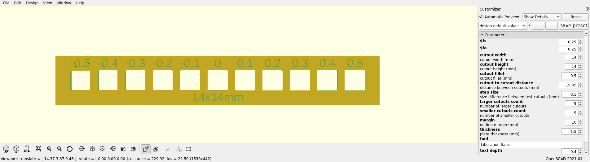
I used OpenSCAD so you can easily adjust the cutout size for different switch types. All files can be downloaded from this printables page. In my case, the 13.9x13.9 mm cutout fit best.
Generating DXFs with kle-ng #
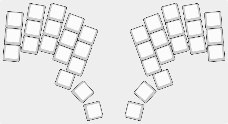
Open our layout in kle-ng. It should be rendered in the preview window like this:
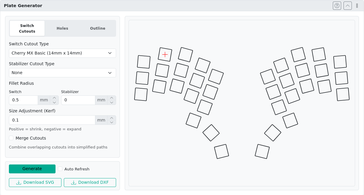
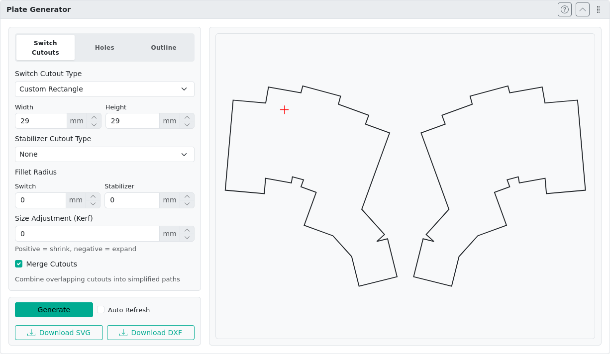
Navigate to the Plate Generator section. Choose the switch cutout type (I will be using Cherry MX switches) and adjust the kerf value according to your calibration print. Remember to account for the sign change: shrinking is represented by positive values, expanding by negative. I’m using a kerf of 0.1 mm to shrink cutouts to 13.9x13.9 mm. Then click the Generate button and download the DXF result. Save it as cutouts.dxf.
Note that by default the generated file does not include outlines. We could navigate to the Outline setting tab and enable them, but kle-ng currently supports only rectangular outlines (blue on the image below), which does not really fit our ergonomic layout.
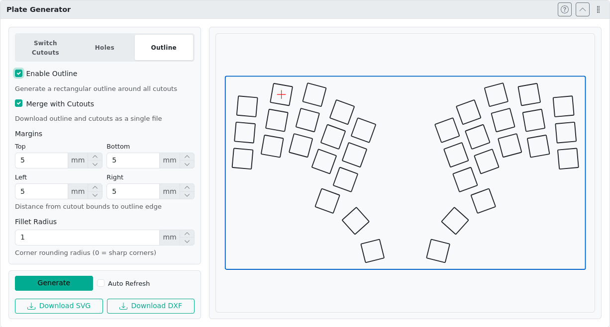
Instead, we can use the Custom Rectangle switch cutout type, for which we can define our own dimensions. Combining this cutout type with the Merge Cutouts option gives us a decent starting point for our outline. This approach saves us some work later in FreeCAD. I will be using 29x29 mm cutouts. It is also a good idea to disable fillets and kerf. We will use this shape to create the actual outline in FreeCAD, so keeping it simple will make it easier.
Download this DXF and save it as outline.dxf. Both files can also be found here.
Prototyping in FreeCAD #
If this is your first FreeCAD encounter, I encourage you to read the Getting started guide.
Importing DXFs and converting to sketches #
Start by creating a new project. Choose Parametric Part from the start menu or start a blank project and use Create body from the Part Design Workbench.
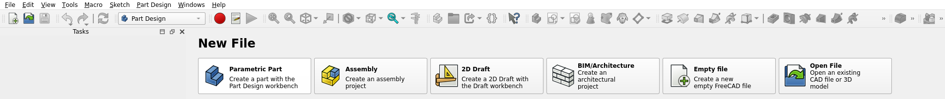
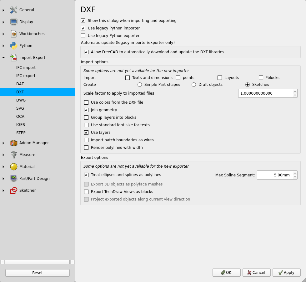
Then select File->Import and choose the outline.dxf generated in the previous steps. By default, the DXF importing settings should appear. Switch to the legacy Python importer, tick Create Sketches, and enable Join geometry. Then confirm with the OK button.
If the import settings did not appear, go to Edit->Preferences->Import-Export->DXF; perhaps you have the Show this dialog when importing and exporting option disabled.
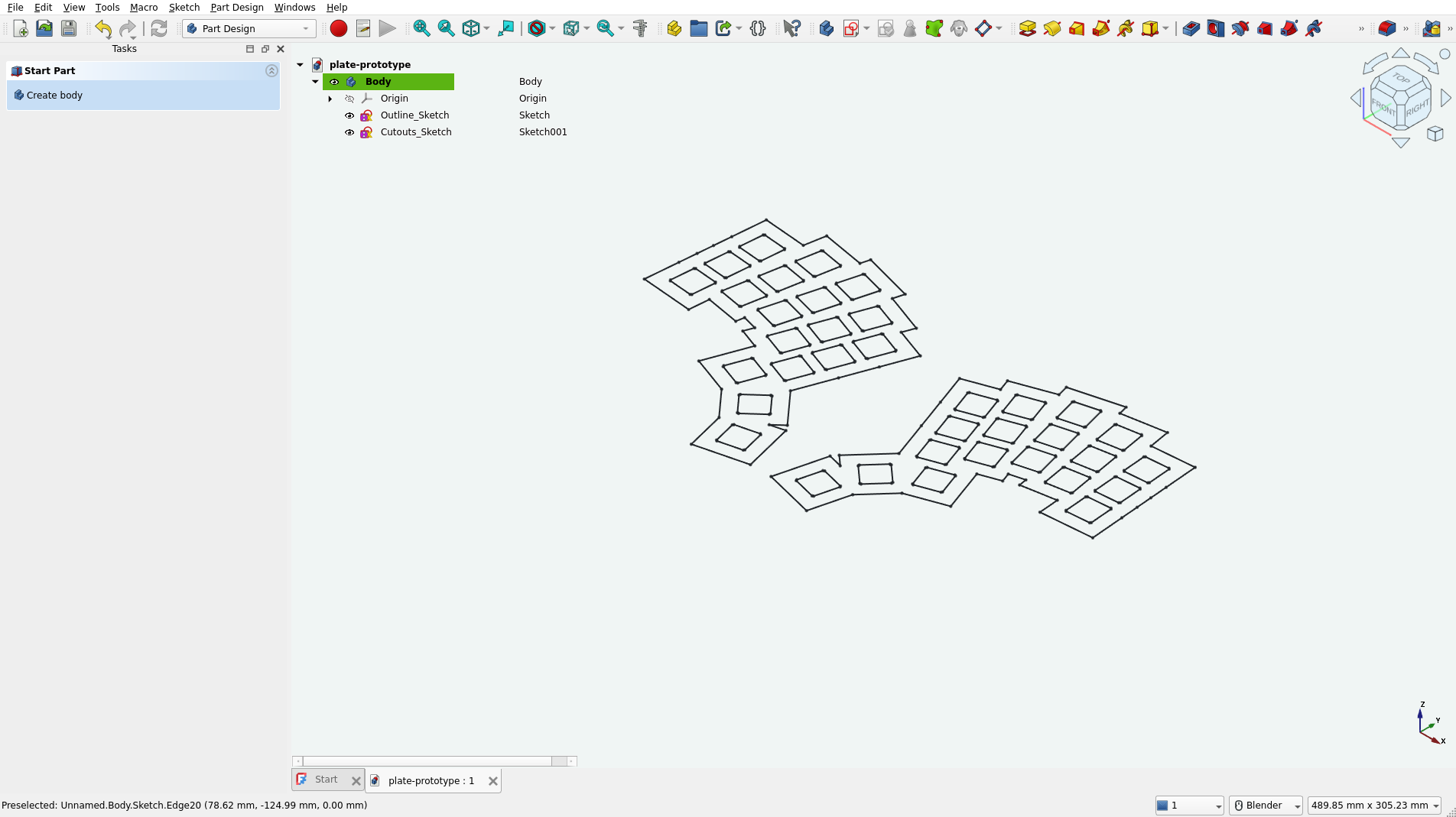
After the import completes, you should see new objects in the Tree View. Remove Wire and Shape as they are not needed. Keep Sketch and our initial Body.
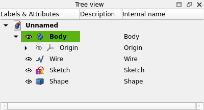
Rename the sketch to Outline_Sketch (using the right-click context menu or F2) and then run Move object to another body (also from the context menu). Confirm our body - it should be the only choice. It is also a good idea to save our Unnamed project before we continue.
Now repeat the DXF import steps and the move-sketch-to-body procedure for our cutouts.dxf file. By the end of it you should have the following result:
Creating the plate body #
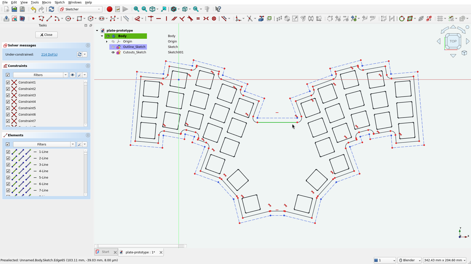
Now double-click on Outline_Sketch to open it in the Sketcher workbench. We will use this workbench to clean up our outline.
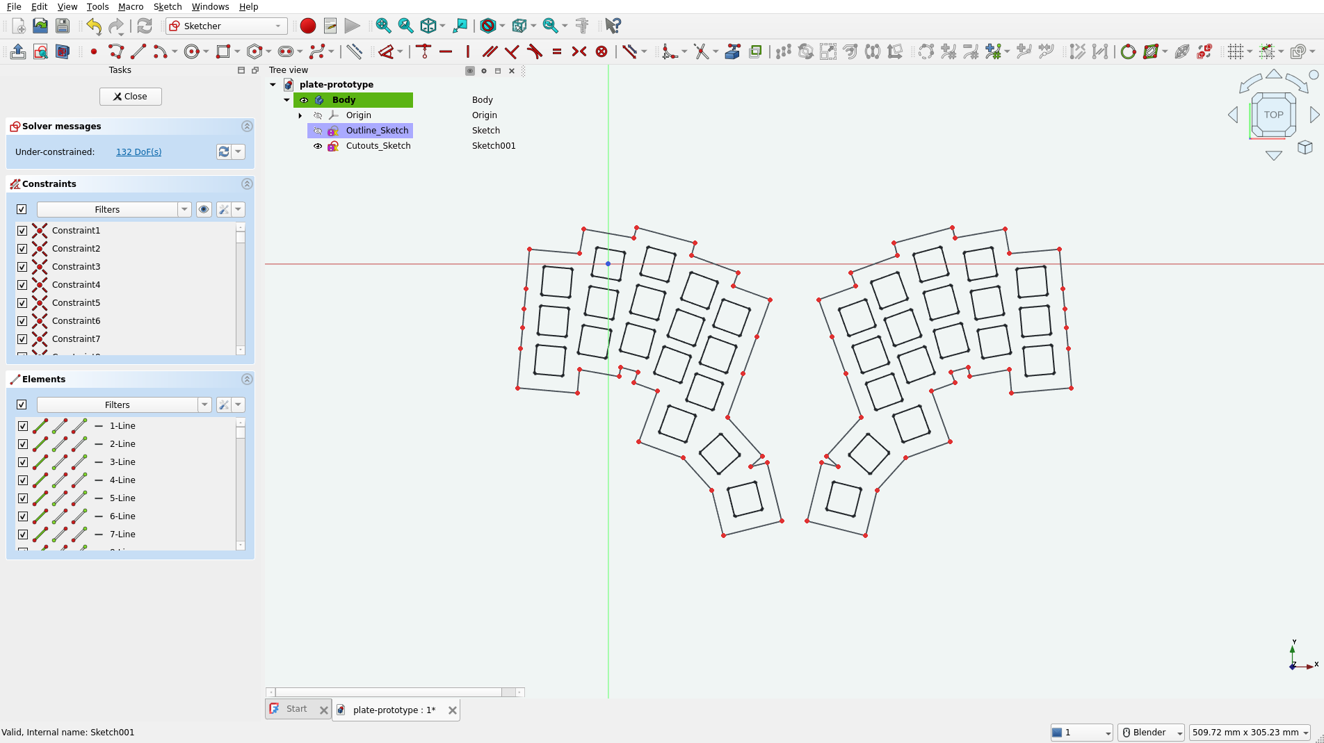
I will do this by selecting the Trim Edge tool and removing some lines by clicking on them.

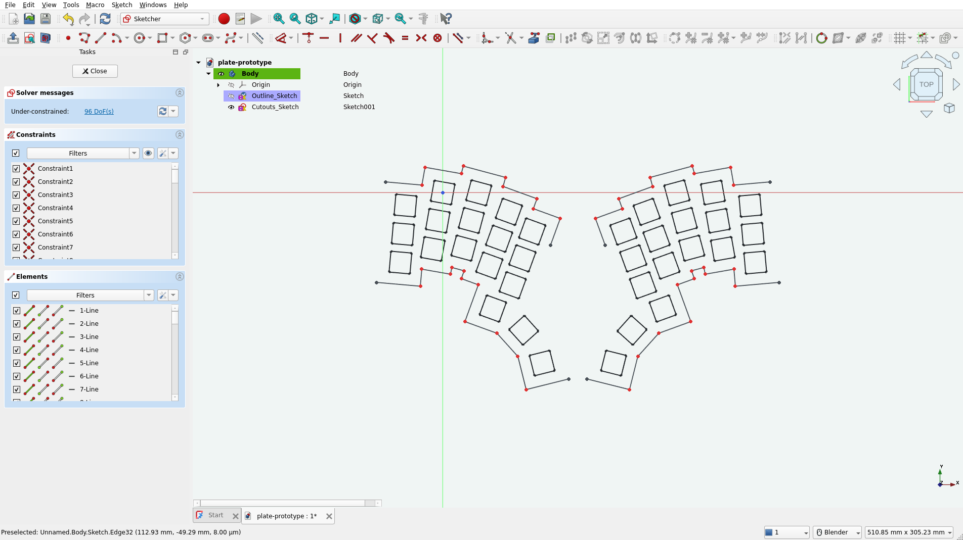
Note that I also removed the side edges. Originally they were composed of 5 collinear segments (indicated by dots). That’s an artifact of kle-ng’s cutout merging algorithm. To make our outline cleaner, I will replace them with proper single edges. Select the Create line tool and draw lines. Start at the vertices. Confirm that your lines are snapping to the ends of the existing segments. This is important because we must have a closed loop at the end. Read the Drawing aids documentation if needed.

This is my result:
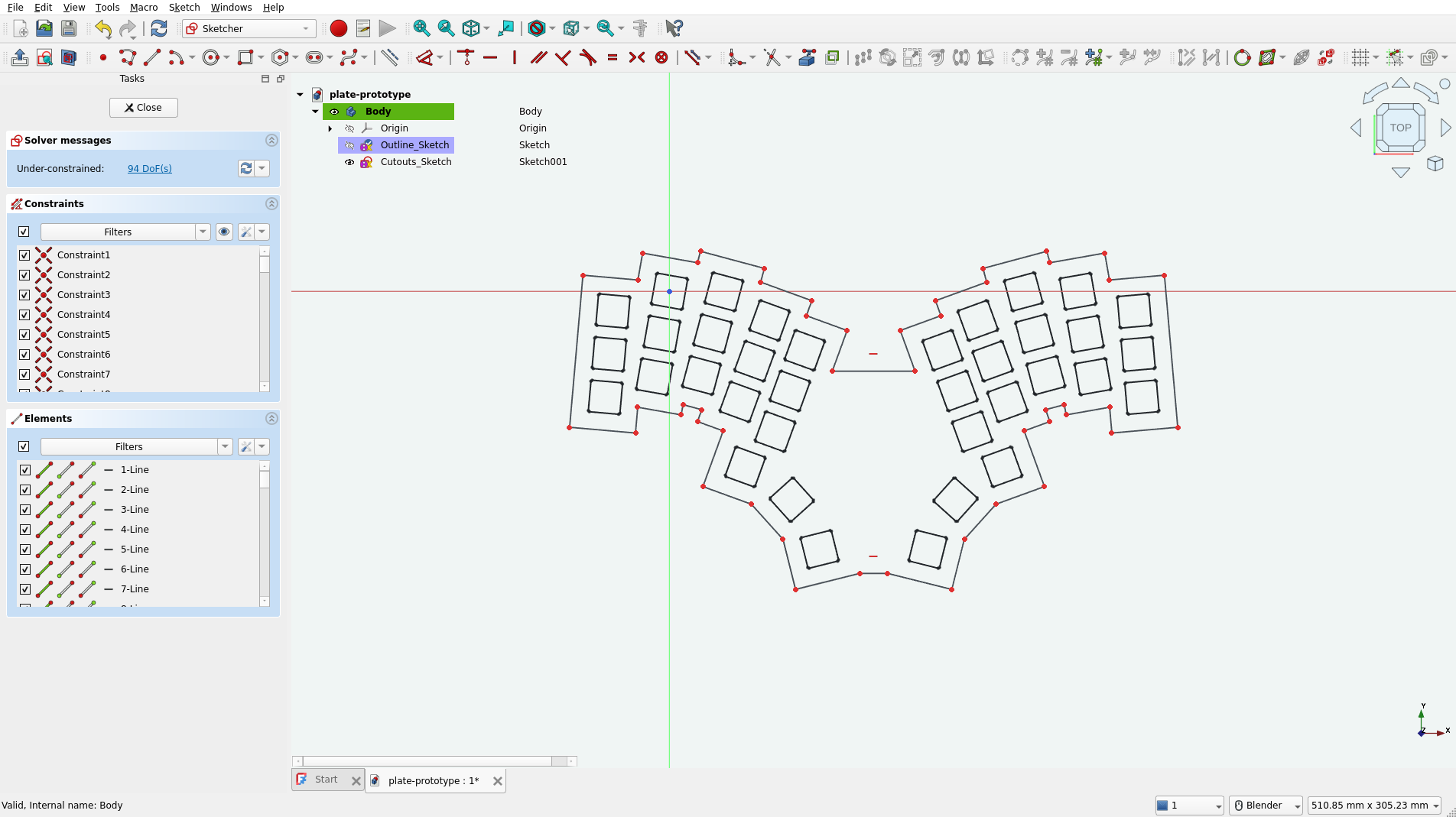
Remember that the outline was created by merging 29x29 mm rectangles. This means that the margins around the cutouts are larger than necessary. This can be easily fixed with the Offset geometry tool. First, select all segments and convert them to Construction geometry:

Our outline should change to a blue dashed line. Then select all again and choose the Offset geometry tool:

With this tool active, move the mouse inside our outline. The generated offset shape should appear. To set a precise value, type the offset size. I used -4 mm.
Finish editing the sketch by pressing the Close button in the Tasks panel. Your result should look something like this:
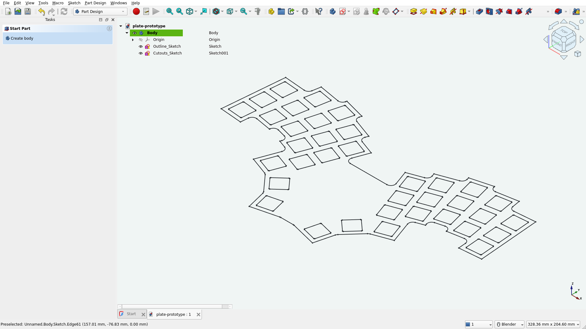
Now select Outline_Sketch and create a Pad. Set the length to 1.5 mm and confirm.

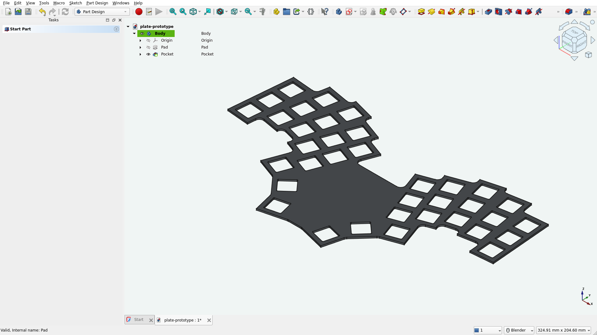
Then select Cutouts_Sketch and create a Pocket. In the type dropdown, select Through all and check the Symmetric to plane option.
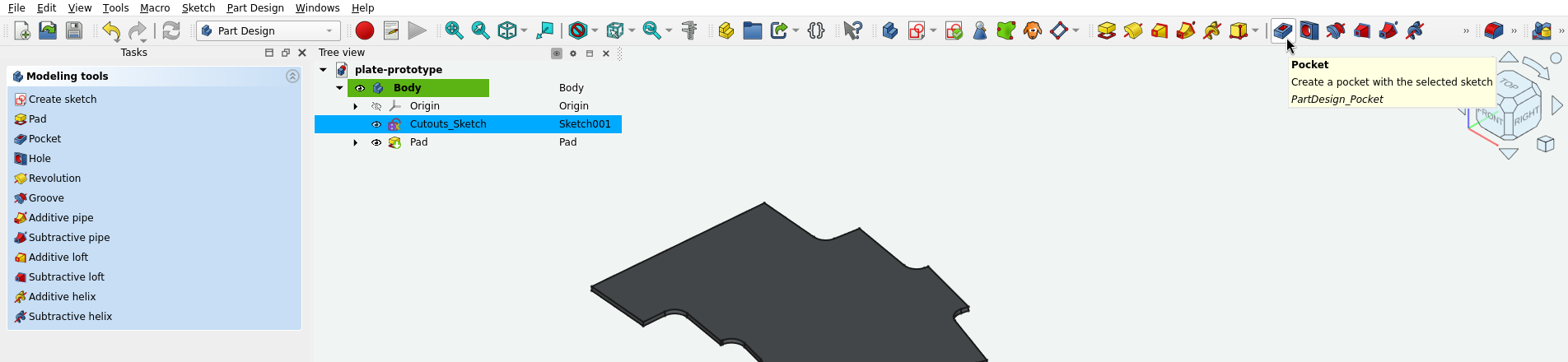
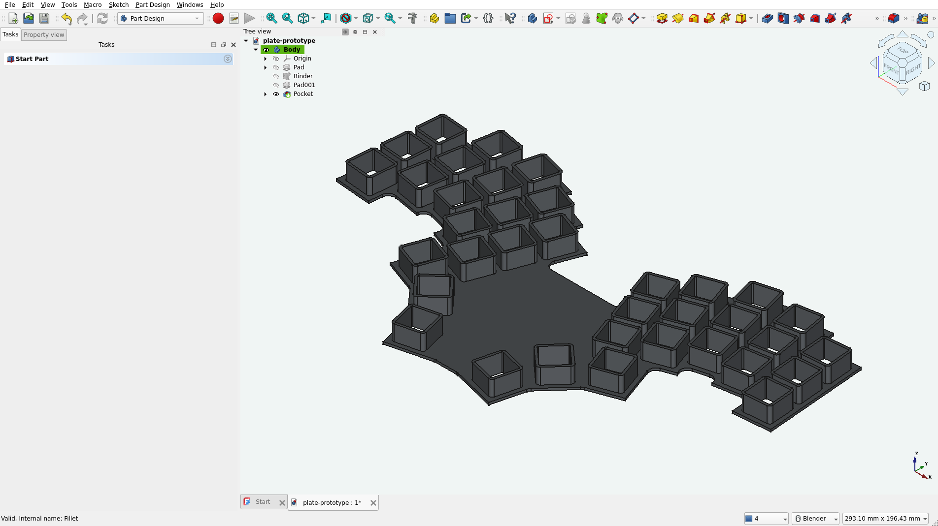
At this point our plate looks like this:
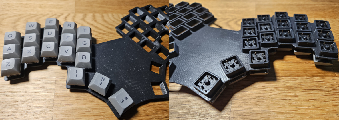
It is almost ready for 3D printing, but I would also like to add some extra thickness around the key cutouts. This way I could use this prototype directly on the table without risking switch damage or table scratches. You will see what I mean in a second. This idea comes from A.dux Ergogen preset layout and it is more material-efficient than simply increasing the full plate thickness. I will show a comparison in the slicer at the end.
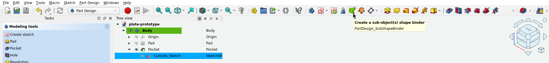
Fortunately, this is an easy operation. Expand our Pocket in the tree view, select Cutouts_Sketch, and use Create a sub-object(s) shape binder.
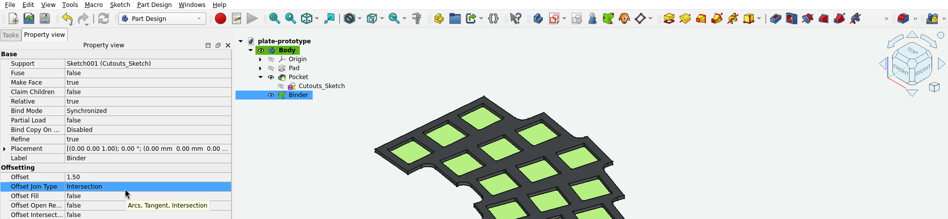
Then go to this binder’s Property view (if closed, open it using the context menu after right-clicking on the binder in Tree view).
Edit the Offset property. This will be our wall thickness. I’m using 1.5 mm (same as plate thickness). Through some trial and error, I also found that it is important to change Offset Join Type from the default Arcs to Intersection. Although both options produce the same-looking binder shape, the first one would give me some open edges when exporting the result to STL. A printer slicer could easily fix them, but avoiding STL artifacts is preferred.
Then create a new Pad out of our binder.
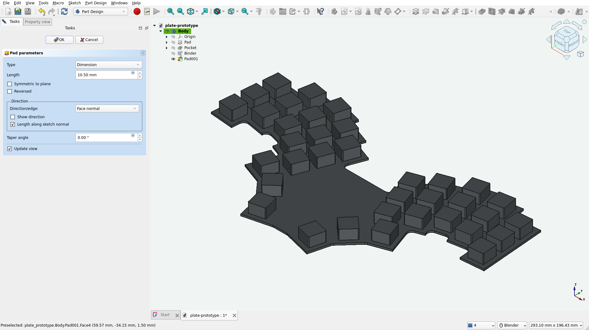
Set its length, remembering that this is measured from the reference surface, so add our plate thickness (1.5 mm) to the height you want to achieve. Anything above 8.5 mm should cover switch pins when mounted (see that switch datasheet again).
The last thing to do is to rearrange our objects a bit. Note that we lost our cutout holes because they were created before this extra pad. Right-click on the Pocket and select Move object after other object.
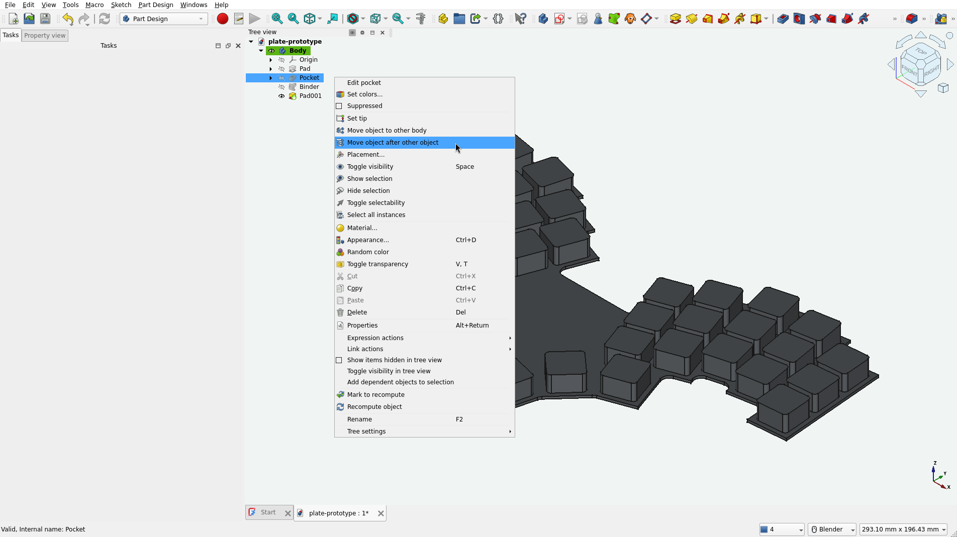
Choose Pad001 and confirm (if nothing has changed, make sure that the visibility of Pocket in Tree view is turned on).
We could stop here, but the last thing I would like to add is fillets to the plate corners. We could go back to the outline sketch and adjust it, but I will be using Part Design’s Fillet tool. Adding fillets is straightforward; I will spare you the details. Read the documentation if needed.
Exporting to STL and printing #
To export to STL, select the last feature in Tree view (fillet in my case) and use File->Export. Choose the STL file extension. Alternatively, you could use the Mesh workbench, which gives you more control over the mesh generation process, but I find the defaults used by Export good enough.
The details on how to go from here to the actual printed part will vary depending on your setup. I’m using Prusa Slicer with my Prusa Core One printer. Fortunately, when rotated, the part fits the print bed.
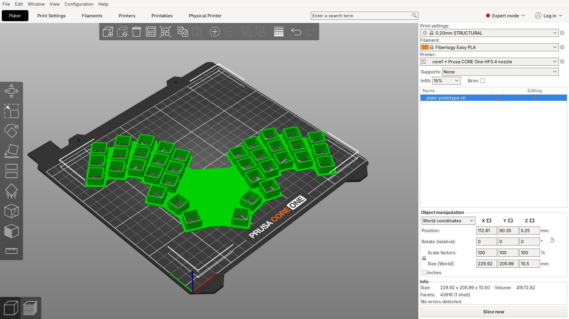
This print took around 2.5 h and used 52 g of plastic. An equivalent thick plate, without our cutout walls, would print in 3.5 h and use 24 g more material.
Summary #
With kle-ng and FreeCAD, you can go quickly from a keyboard layout to a 3D-printable plate prototype.
- Calibrate first - a small test print with varied cutout sizes saves time and filament compared to reprinting the full plate.
- Generate two DXFs from kle-ng: one for switch cutouts (with size adjustment) and one for the outline (using Custom Rectangle with Merge Cutouts).
- Import DXFs into FreeCAD with the legacy Python importer and Join geometry enabled to get clean, closed sketches.
- Clean up the outline in Sketcher - trim extra edges, redraw collinear segments, and use Offset geometry to tighten margins.
- Build the plate with Pad and Pocket, then add reinforcement walls around cutouts using a SubShapeBinder with an offset.
Many of these techniques apply just as well to a final production plate, not only prototypes. In this particular case, I’m glad I prototyped first - it turns out I’m not a fan of this layout. Better to find that out with a quick print than after committing to a full build.