Keyboard PCB design with ergogen and kbplacer
24.02.2024Let’s create KiCad project using ergogen and kbplacer. Although ergogen is capable of generating KiCad PCB files, I will be using it only to create key matrix layout. This will result in more traditional KiCad project structure including schematic.
Footprints placement and some initial routing will be handled by kbplacer.
Get ergogen points file #
Ergogen configuration is beyond the scope of this tutorial, for simplicity I will be using web-based deployment at ergogen.xyz.
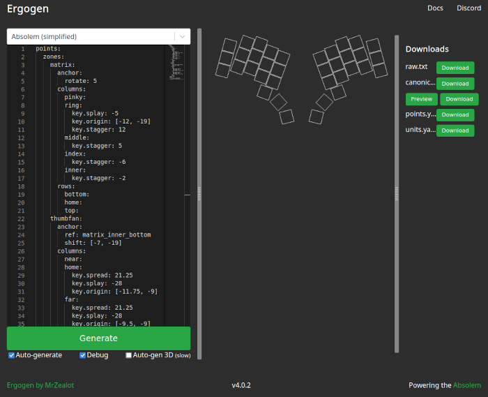
To learn how this ergogen’s layout description format works see ergogen docs.
For demonstration purposes I selected Absolem (simplified) preset to which I added
rows and columns nets. This is not required but it will save me some work in next step.
Details about matrix annotations can be found in flatfootfox guide.
| |
Now I can run Generate and download points.yaml file which will be used by kbplacer.
ergogen version may require enabling ‘Debug’ setting to generate points.yamlConvert ergogen points to KLE layout #
From now on, I will be using kbplacer which is python package using KiCad’s python API. For installation options see installation guide.
First I will install it in virtual environment in newly created project directory:
| |
On Windows use python distributed with KiCad, otherwise kbplacer will not have access to KiCad’s bindings.
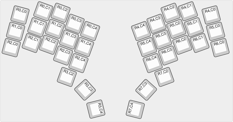
Now, to convert ergogen points file to KLE layout run:
| |
kbplacer version use double dash (--) instead of single dash (-) for CLI argumentsThe resulting file can be imported by keyboard-layout-editor:
Generate KiCad schematic #
To generate KiCad schematic I will use example kbplacer tool which currently is not a part of the package itself. It is just a single script with one dependency so it should be easy to run. Within previously initialized python virtual environment run:
| |
To generate new schematic file run:
| |
The result should be as following:
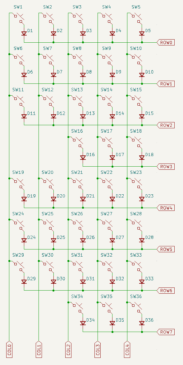
Generation of MCU circuit is not automatic. It can be added later, for this tutorial I skip it entirely.
Remember to assign footprints to symbols. To do it in bulk use Tools->Asign Footprints....
Then create PCB and import changes from schematic.
In order to place and route imported footprints, use kbplacer again. For details
how to use it from CLI see python -m kbplacer --help output.
In order to use it with GUI from KiCad, install it as kicad plugin. Plugin icon will appear on the toolbar. Start it to see something like this:
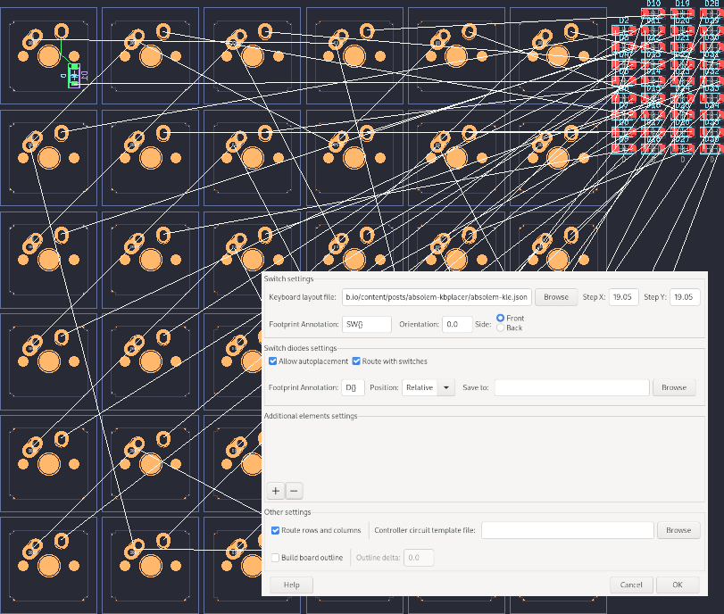
In this instance I’m using previously generated layout file with Relative position diode option
and automatic routing enabled. This way the plugin will replicate my first switch-diode pair connection for
remaining switches. See options overview to learn more.
After clicking OK I got following result:
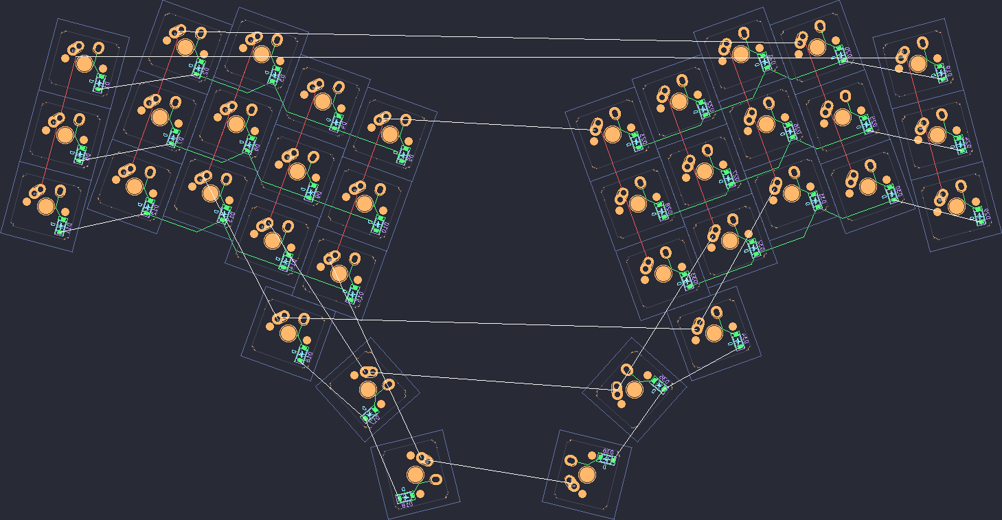
And that is all. The process requires some manual steps (i.e. assigning footprints, importing schematic to PCB) but it can be fully automated (see this).